Saturday, November 30, 2013
Thursday, March 28, 2013
Some Calvin & Hobbes Comic Strips

 |
| July 31st 1992 |
 |
| August 21st 1992 |
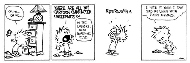 |
| September 5th 1992 |
 |
| Spetember 19th 1992 |
 |
| September 24th 1992 |
 |
| October 6th 1992 |
 |
| October 9th 1992 |
 |
| October 13th 1992 |
 |
| November 2nd 1992 |
 |
| November 18th 1992 |
 |
| November 20th 1992 |
Types of Bag Making Machines
- 3-Side Seal
 Here, a film reel is fed into the machine, this reel is passed through a set of rollers so as to be slit into exactly half and placed one on top of the other. The two overlapping films are then passed through plates which have been pre-adjusted for the pouches specifications and then they are with proper tension, heat-sealed on the two sides. A pre-calibrated sensor is then used to seal the final end after the reel has moved a certain length. The final process of this involves the slitting at the same regular intervals in order to create a three-side seal pouch.

- Gusseted Seal
 This consists of two processes. First, a film is fed into the machine which seals both the ends together forming a continuously closed package with two open ends. This is reeled and fed into another machine. Here, the film is subject to blowing and is then proceeded to more adjustable plates where the sides are gusseted. As it is reeled in form one end, with the proper tension, it's heat-sealed and slit with the help of a sensor placed in the machine to produce a gusseted pouch.

- Centre-Seal (with Gusset Option)

 Here a film reel is fed into the machine and it's passed through a set of manually-adjusted plates that would fold the reel so that it's ends touch each other. This is then heat-sealed forming a centre-seal. As it is reeled in form one end, with the proper tension, it's heat-sealed on the other end and slit with the help of a sensor placed in the machine to produce a centre-sealed pouch, with proper adjustment, a gusseted centre sealed pouch is allowed to be manufactured.


Wednesday, March 27, 2013
Film Blowing Process

Film Blowing is the process of forming polythene sheets or a film using polythene pellets. The pellets are first crushed and melted into a viscous liquid. This molten liquid is then extruded vertically through a die. Air is injected through the centre of the die forming a balloon-like shape from the extruded polythene. The air entering replaces the air leaving thereby giving the extruded material a uniform thickness throughout.
As the extruded polythene is moving vertically upwards, and it passes through a cooling ring where the material gradually solidifies. Upon completion of the solidification process, the material is passed a set of nip rollers which flatten it and collapse the balloon-like shape resulting in the formation of two flat film layers. The films are then wound up on idler rolls to ensure uniform tension is applied through it. The film layers are also then corona treated to increase its surface adhesiveness, so that effective lamination occurs.
A recommended composition of 80% LLDPE (Linear Low Density Polyethylene) and 20% of (Low Density Polyethylene) is used in this production. There are machines with two inlets and machines with three inlets for pellets. Thereby by using different coloured pellets, a sheet of varying colours can be extruded. Even certain materials like nylon can be used in the mix for a variety of properties.
 |
| Film Blowing Process |
Production of High-Impact Polystyrene (HIPS) cups

The production of High-Impact Polystyrene (HIPS) cups are described below.
Polystyrene pellets that are exported along with recycled, crushed PS fragments are fed into a Sheet Extrusion Machine. Here the pellets are heated through a barrel and are formed into sheets. By using different coloured pellets, the sheet and hence the colour of the cups can be customised. This sheet is collected into a reel and fed into the next machine, the Moulding Machine.
The sheet is fed into a moulding machine and here, the HIPS cups are vacuum moulded into it's desired shape. The cups upon being moulded are removed from the machine and collected altogether for printing, the final process in the HIPS cup production.
The “blank” cups are fed into a HIP cup printer which utilises UV light for its printing. The printer can accommodate 6 colours each are pressed onto a blanket that is connected to a drum. The drum passes through each HIPS cup which deposits a uniform amount of ink on each HIPS cup. The HIPS cups are then treated with UV light where the ink is dried,
The HIPS cups are then collected and are now ready for delivery.
The advantages of HIPS as a material are that with low cost, the material has a very good impact resistance, machinability and dimensional stability. In addition to that, it has very good aesthetic properties as well as is very easy to paint or glue on to.
Monday, March 25, 2013
Tension on Rollers
The tensions applied on the substrates are closely monitored . This is done with the help of a load cell. A load cell is able to convert a force exerted on it by means of deforming a strain gauge which in turns measures this deformation applied on it into an electrical signal. This electrical signal varies when different forces are applied because the strain gauge's electrical resistance varies by the degree it's deformed. A strain gauge is a length of conductor arranged in a zigzag pattern in a membrane whose electrical resistance increases the more it's stretched. The voltages are normally in the order of millivolts and require amplification before it can be used to measure anything.

Normal load cells consists of four strain gauges arranged in the Wheatstone configuration, but the one in this context utilises only two strain gauges arranged in a half bridge configuration as shown below and is calibrated as such to indicate the tension in terms of kilograms, as this is a more common unit that technicians are more accustomed to.
According to the machine operators, the normal operating tensions for the Aluminium foil are around 12 kilograms worth of pressure whereas the PET will require something in the order of 9. With the help of the load cell, it is much easier for operation as the right amount of tension is easier to be applied. With the right tension applied on the substrates, the chances of creasing or wrinkling occurring is reduced drastically.
An improvement to the existing system is the implementation of a Tension Roll Transducer. The Tension Roll Transducer is combined with a regular idler roll consisting of 2 load cells. The reasons as to this being recommended in all the machinery are as follows:
- Measures and displays the actual web tension and allows for the control of the tension too.
- Since they are all assembled into one unit, there no assembly required whatsoever.
- Costs less than an idler roll and a load cell bought separately.
- Easy to install and takes up the same space as an ider roll.
- Only one transducer cable hence no cables will cross the machine.

In addition to that, the bearing on the nip roller were also replaced as it was observed to not have a stable rotation and it was believed to be one of the reasons for the formation of creases on the final laminate.
Half-Bridge Load Cell

- Two active strain-gauge elements. One is mounted in the direction of axial strain, the other acts as a Poisson gauge and is mounted transverse (perpendicular) to the principal axis of strain.
- Completion resistors provide half bridge completion.
- Sensitive to both axial and bending strain.
- Compensates for temperature.
- Compensates for the aggregate effect on the principle strain measurement due to the Poisson's ratio of the specimen material.
- Sensitivity at 1000 me is ~ 0.65mVout/Vex input.
The following symbols apply to the circuit diagram and equations:
- R1 and R2 are half-bridge completion resistors.
- R3 is the active strain-gauge element measuring compression from Poisson effect.
- R4 is the active strain-gauge element measuring tensile strain.
To convert voltage readings to strain units use the following equation:

To simulate the effect on strain of applying a shunt resistor across R3, use the following equation:

Subscribe to:
Comments (Atom)